XR650L Hot Cam Installation Guide
- rcl5011
- Aug 19, 2023
- 9 min read
Updated: Nov 4, 2023

Table of Contents
Overview
This installation guide will cover how to install a Hot Cam into an XR650L, as well as the break-in procedure. Please note that these images throughout the guide show a motorcycle that was in a more significant state of disassembly than is required.
Technical Specs
Lift and Duration:
Exhaust Cam Lobe Duration at 1mm 258°
Exhaust Cam Lobe Lift 8.80mm
Intake Cam Lobe Lift 8.80mm
Intake Lobe Duration at 1mm 258°
Rocker Arm Lash:
Exhaust Cam Valve Lash 0.20mm (.008in)
Intake Cam Valve Lash 0.15mm (.006in)
Tools Required
8mm, 10mm, 12mm, 14mm, 17mm Sockets
5mm, 6mm, 10mm Hex Wrench
10mm, 12mm Closed End Wrench
Spark Plug Socket
Torque Wrench
Flat Blade Screw Driver
Pliers
Feeler Gauges
Zip Ties
7/16in or 3mm drill bit (or dowel pin)
Gasket Scraper
Components and Chemicals Required
Engine Assembly Lubricant
Disassembly
Heat up the engine and drain all engine oil.
Remove the seat using a 12mm socket on the bolts under the rear fender as shown.
Remove the gas tank by disconnecting the fuel line to the carburetor using a pair or pliers, and then remove the mounting bolt using a 10mm socket.
Remove the spark plug using a spark plug wrench. This allows the engine to be rotated freely without resistance from compression.
Remove the front and rear engine mounting brackets and bolts using a 14mm socket

Remove the top engine mount using a 14mm socket, and then remove the braided oil line by pinching and sliding the hose clamp while pulling on the line.

The engine should now be able to be rotated about the last remaining rear bolt passing through the engine. If required, loosed but do not remove this last remaining bolt to get the engine to rotate downward such that the cylinder head moves away from the frame rail and provides additional clearance to remove the cylinder head cover.
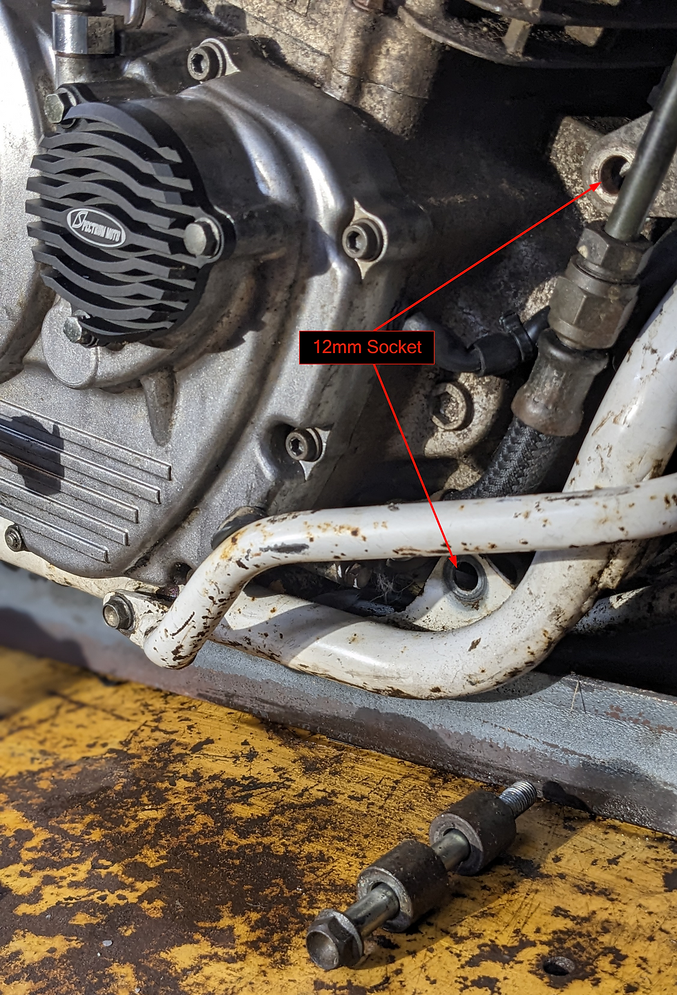
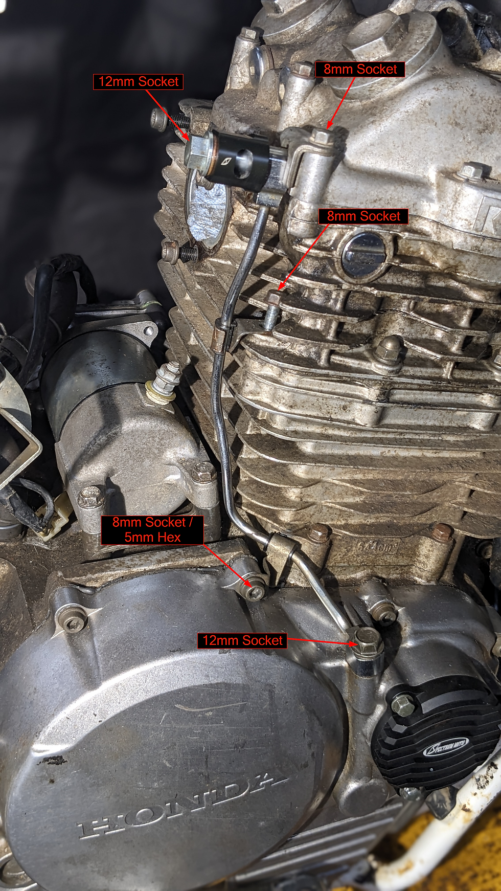
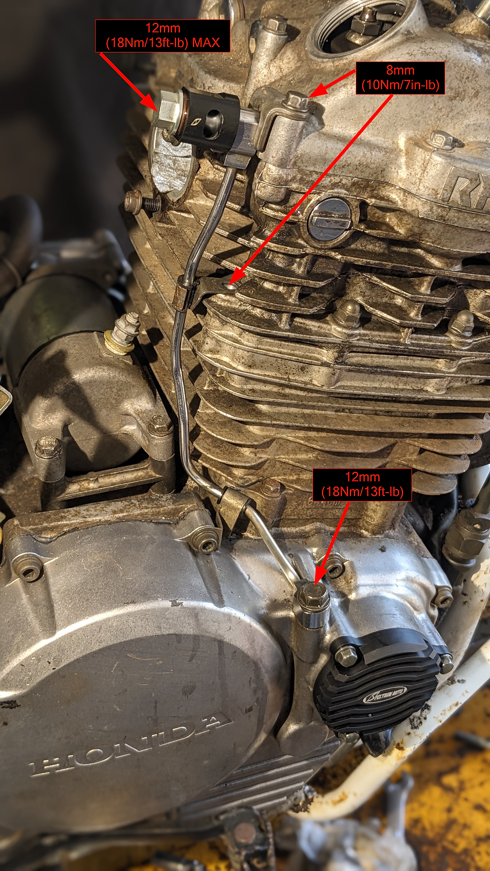
Remove the oil line from the crankcase to the cylinder head using an 8mm and 12mm socket (older models may require a 5mm hex). When removing the oil line, it is highly recommended to replace the copper crush washers. If you plan to re-use the washers it is CRITICAL that you keep them in the exact same orientation and position as they were when removed.
Next, remove the inspection covers on the stator side of the engine using a 6mm and 10mm hex wrench.

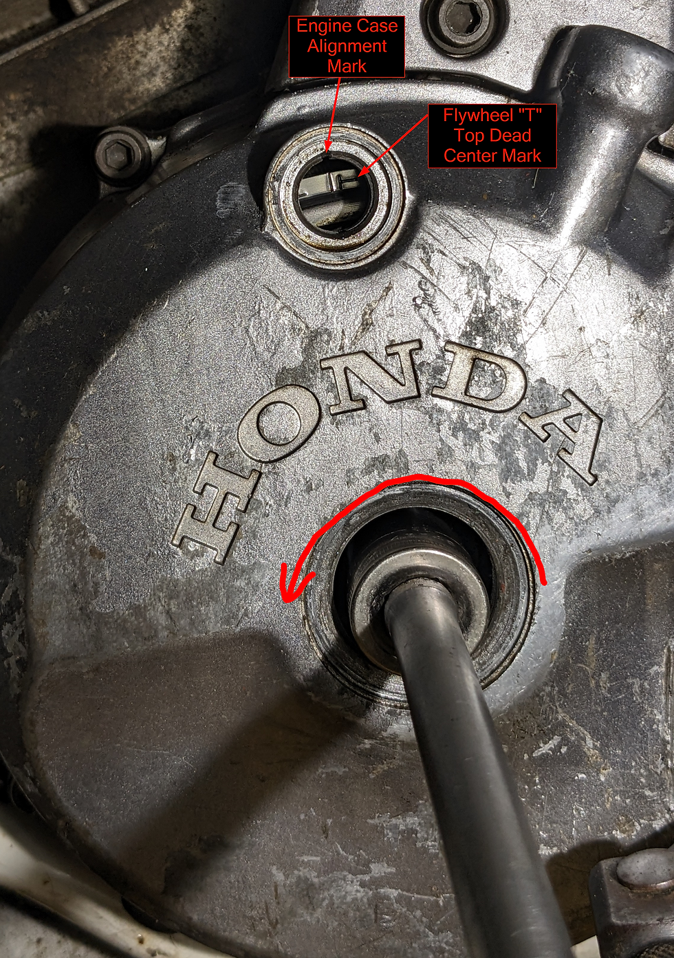
Using a 17mm socket, rotate the stator COUNTER CLOCKWISE until the alignment mark on the engine case aligns with the "T" on the flywheel to indicate top dead center.
Remove all bolts holding the cylinder head cover in place using a combination of 8mm and 10mm sockets, as well as a 10mm wrench.
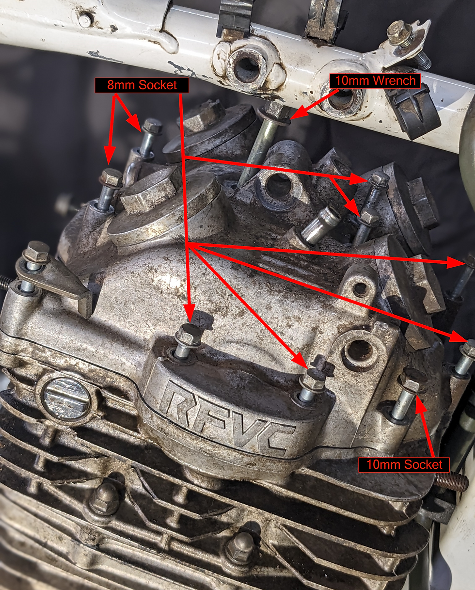
Remove all of the bolts except for the center bolt that required a 10mm wrench, along with the rocker arm adjustment covers and then pick up the cylinder head cover and pull it out in a direction that is roughly in a 45deg angle simultaneously to the rear and left side of the bike. Be sure to pick up on the 10mm center bolt as you remove the cover to eliminate the possibility of it getting stuck on part of the engine. (Yes, the images do not show us removing all of the bolts or the rocker arm inspection covers, but you'll have a much better time if you do).

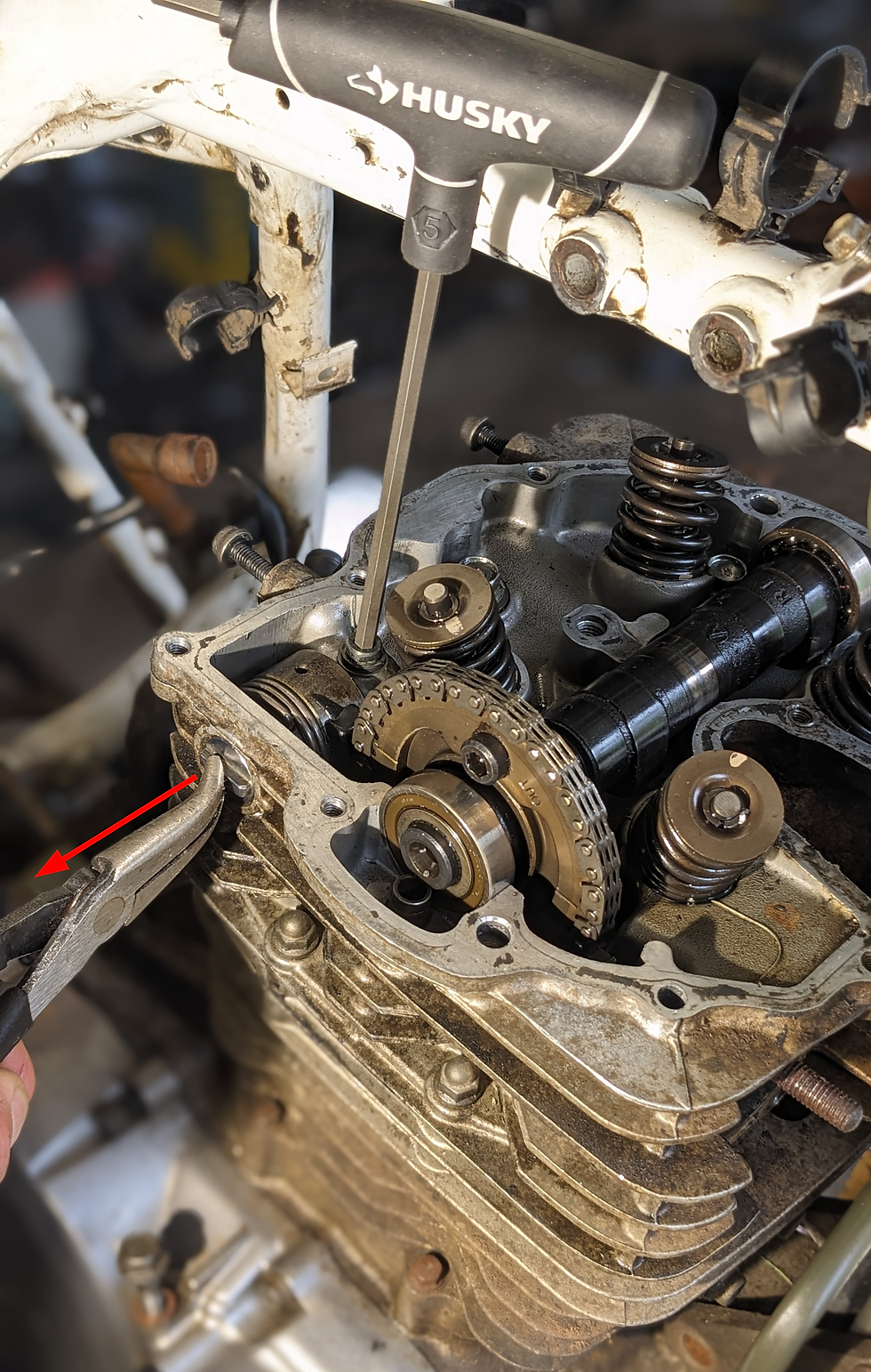
Once the cylinder head cover has been removed, the cam chain tensioner must be removed. Start by removing the bolt that holds the pivot shaft in place using a 5mm hex wrench. Then pull outward on the pivot shaft using a pair of pliers.
Now push upward on the cam chain tensioner through the pivot shaft hole and remove the tensioner assembly.

Remove the camshaft sprocket bolts as shown below using a 6mm hex wrench. You will need to rotate the flywheel 360deg in order to rotate the cam sprocket 180deg to remove the second bolt. Ensure that you only rotate the engine in the counter clockwise direction while looking at the flywheel, and re-alight the "T" symbol with the engine case mark.

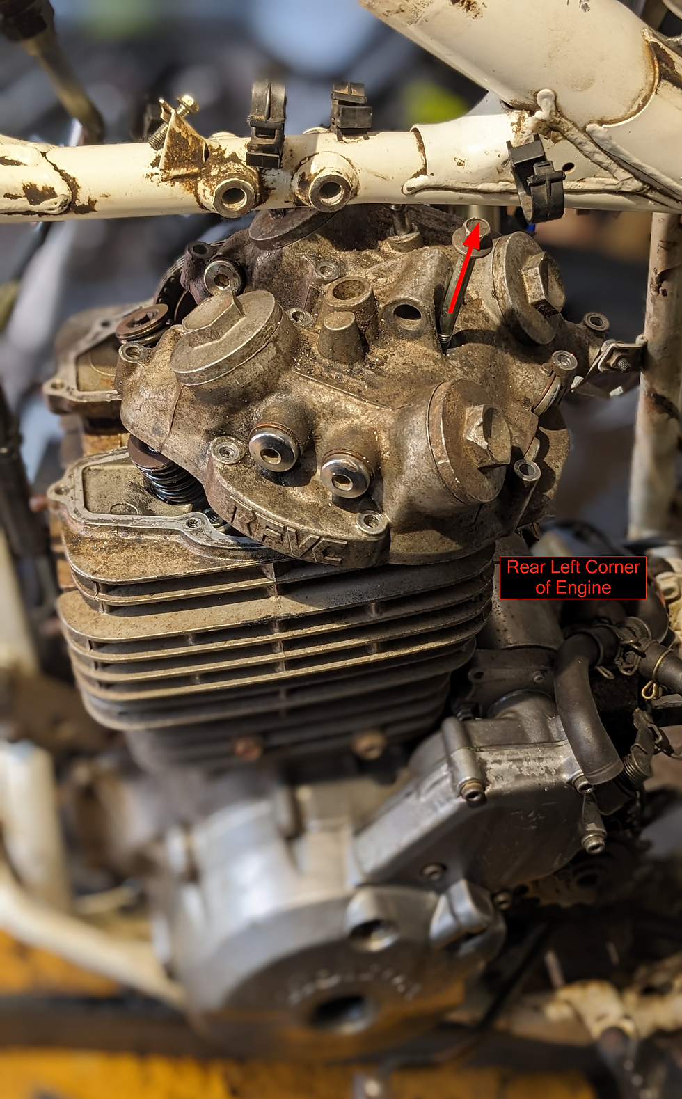
Remove the camshaft to the left side of the motorcycle. The bearings on the cam will easily fall off, so take care as to not drop and damage them. Once the camshaft has been removed, the automatic compression release spring and plunger must be removed from the hole circled in red.

With the cam removed, clean the gasket surfaces with a gasket scraper to ensure the sealing surfaces of both the cylinder head and cylinder head cover are clean.
Assembly
Transfer the bearings from the old cam to the new Hot Cam. If you are replacing the cam for oil starvation reasons, you MUST replace these bearings with those which are brand new.

***CRITICAL***
The sprocket side bearing is sealed on one side only. The sealed side of the bearing faces outward away from the cam. You must install this bearing in the correct orientation.

Prior to installing the cam, double check that the flywheel "T" mark is still aligned perfectly with the indicator mark on the engine case. Next, Install the new cam with the bearings installed into the cam sprocket. The cam shaft sprocket MUST align its indicator marks parallel with the top face of the cylinder head.

Re-install the cam shaft sprocket bolts using Loctite, and then torque to 20N-m (14ft-lb). Rotate the flywheel 360deg to install the second bolt. If the last time you rotate the flywheel the cam lobes are pointing upward, you must rotate the flywheel one final time to ensure that the cam lobes are pointing down.

At this time, the following three points MUST be true:
The flywheel "T" indicator mark is aligned with the indicator on the engine case housing
The camshaft sprocket indicators must be parallel with the cylinder head top surface
The cam shaft must be rotated such that the lobes are all pointing downward

The cam chain tensioner must be reinstalled with the spring pre-tensioned in order for it to properly fit. There is a special tool that Honda sells in order to accomplish this, but it's unnecessary. You will need a zip tie, and a 7/16in (or 3mm) drill bit (or something similar). Hold the tensioner assembly in a vice, ensuring only to hold on the metallic faces below the rubber overmolding, and then follow the steps below.
Create a loop with a zip tie as shown

Place the opposite end of the locking feature of the zip tie around the spring protrusion, and then grasp the spring with a pair of pliers (vice grips are ideal but not required)

While holding the spring tightly, begin to rotate the spring counter clockwise and with the drill bit placed through the zip tie loop, start engaging it into the hole in the top of the tensioner assembly as you lift it upward and fully engage it vertically.


If the spring does not position itself vertically, or slightly counter clockwise from vertical, you will have trouble installing the assembly. You will need to rotate the spring and tighten the zip tie until you achieve vertical or counter clockwise biased spring position.
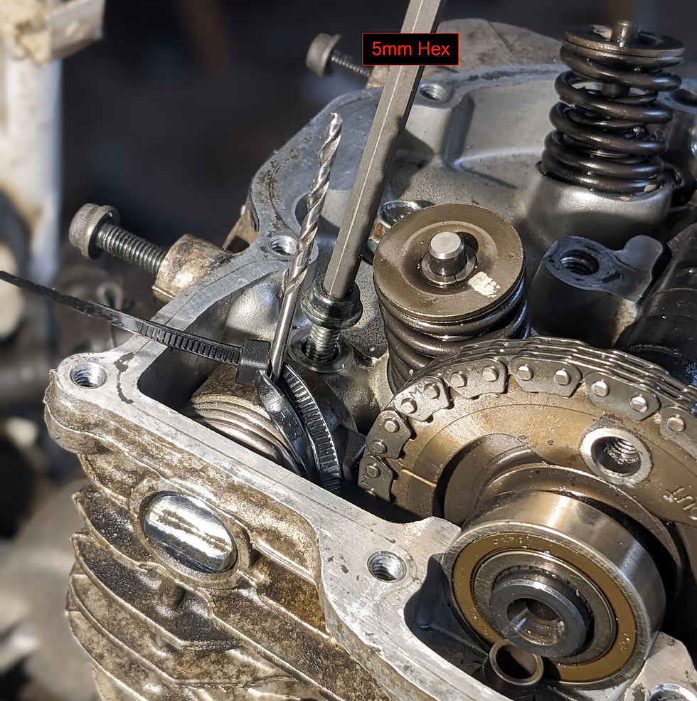
Now, install the tensioner assembly as shown below, and re-install the pivot shaft and retainer bolt using a 5mm hex wrench. Note that the tensioner has a one way bearing, which only allows you to rotate the shaft in one direction. You will need to rotate the pin in order to alight the bolt with the bolt hole.
Next, cut the zip tie and using a pair of pliers, pull the remaining piece of the zip tie out of the engine.

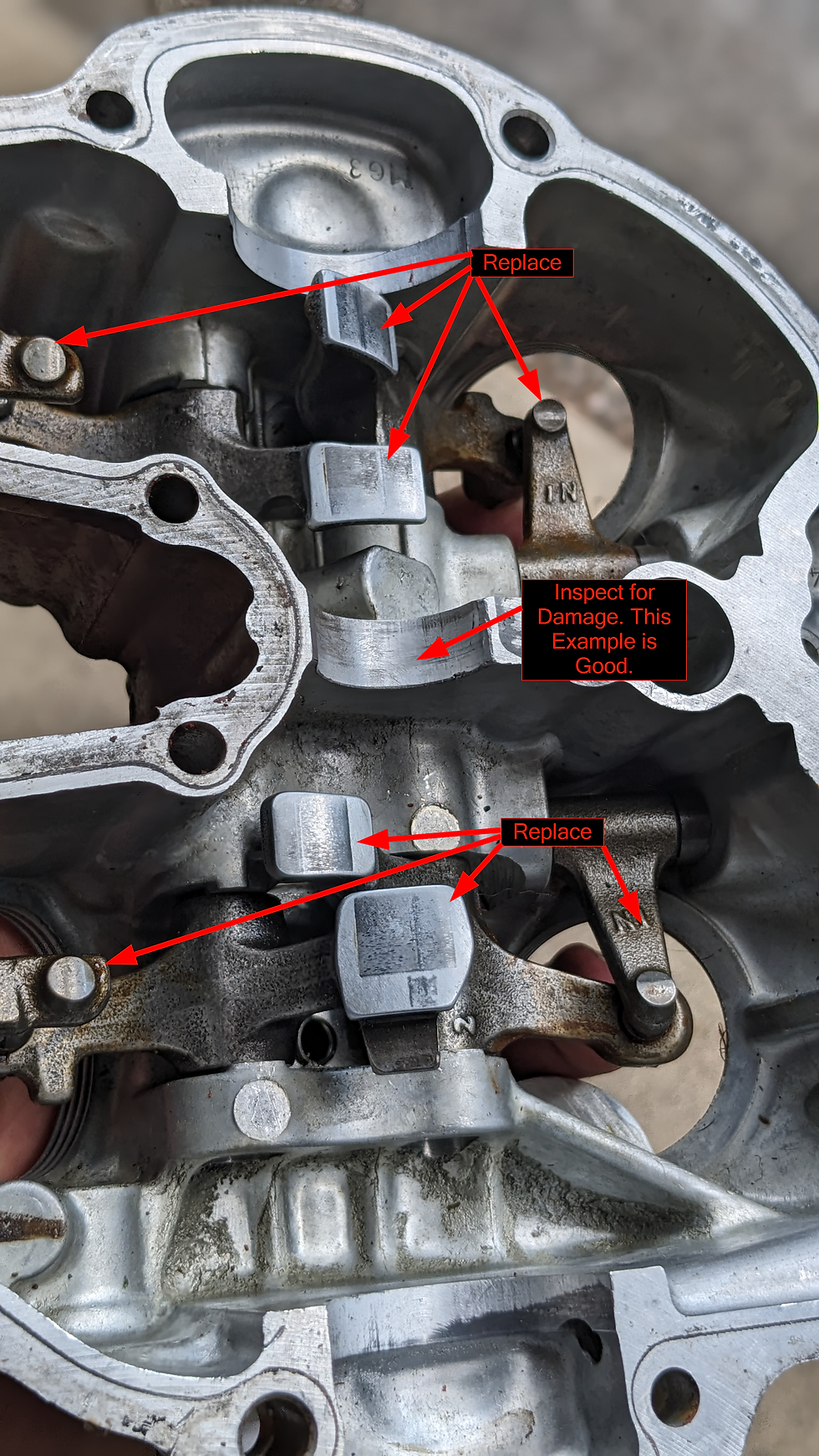
Inspect the cylinder head cover for damage to the cam bearing journal. Also take a look at the rockers and rocker components. If cam bearing journal shows signs of damage, it can be welded and line bored back to specifications, along with the cylinder head bearing journal. XR's Only can provide this service along with a number of other shops.
The rockers arms are recommended to be replaced for any new cam installation. The reason for this is that on a microscopic scale, the cam and rockers wear together and allow maximum surface contact between the two. This maximum surface contact allows for what is known as hydrodynamic lubrication, where a film of oil is maintained between the cam and rockers due to the surface speed of the cam. If you install a new cam with old rockers, the rocker arms have worn into the old cam surface profile and is covered with very small imperfections in diameter in the form of grooves and changes in flatness. All of the small grooves and differences in diameters that exist on the rockers will now be in contact with the new cam. This means that many surfaces will no longer be in contact (only the largest diameter portions of the rockers), causing very high forces and stresses on the small surfaces that are in contact. These high stress points will not support hydrodynamic oil lubrication and will be a pre-mature failure point for your new am and possibly lead to further engine damage. INSTALL NEW ROCKERS!
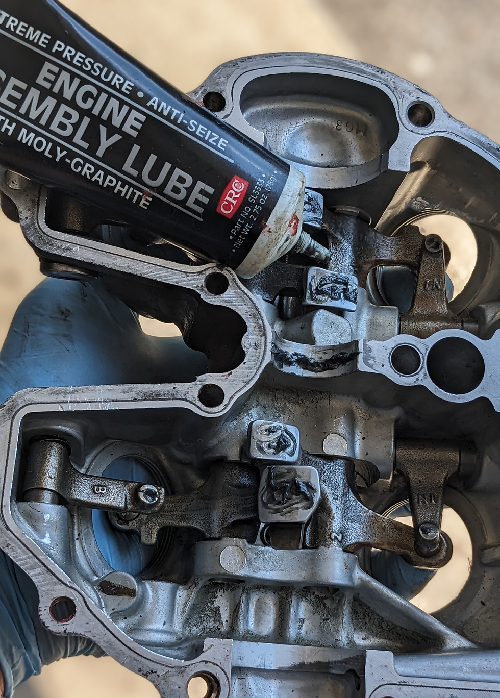
With the cylinder head cover outfitted with new rockers, apply engine assembly lubricant to the cam and rocker faces as shown.

Install a new gasket on the cylinder head cover, and install the central bolt back into the cylinder head cover (this bolt cannot be installed after the cover is in place). Then begin to install the cylinder head cover in the opposite direction it was removed from. Starting from the back left corner of the motorcycle, towards the front right. Hold upward on the central bold during installation to keep it from hanging up on the cam and cam components.
Apply Loctite and install all of the remaining bolts in the cylinder head cover, then torque to spec using 8mm and 10mm sockets. Reinstall the oil line onto the cylinder head cover using the hose clamp.

The oil line from the crank case to the cylinder head is installed next. If running our spectrum moto oil sight glass, the copper washers are of different diameters and must be installed in the order shown below. Do not torque the sight glass beyond 13 ft-lb using a 12mm socket/wrench. If there is oil leakage, replace the copper washers.

Set the correct valve lash on both intake and exhaust valves. You will need a set of feeler gauges. Start by verifying that the flywheel still indicates that it is at top dead center. If not, rotate the crankshaft counter clockwise until the "T" mark is aligned with the engine cover indicator mark. This ensures that the cam is in its dwell position and not pushing up on the rocker arms. Using a closed end 12mm wrench and a flat blade screw driver, loosen the jam nut on each rocker arm as shown below. Hold the flat blade screw driver still, while rotating the jam nut counter clockwise by approximately one 1/4 of a revolution. This will now permit the screw screw driver to adjust the vertical position of the rocker arm

The Hotcam requires specific lash settings for both exhaust and intake valves. The cam card shown below lists the settings.

Starting with the exhaust, use a 0.2mm (.008in) feeler gauge to set the valve lash using the flat blade screw driver. The feeler gauge should not be tight fitting when pushed in and out of the rockers, but should instead just provide a slight drag. Once this clearance has been met, lock the lock nut down and re-verify clearance one final time.
Repeat this step on the intake valves with a 0.15mm (.006) feeler gauge.

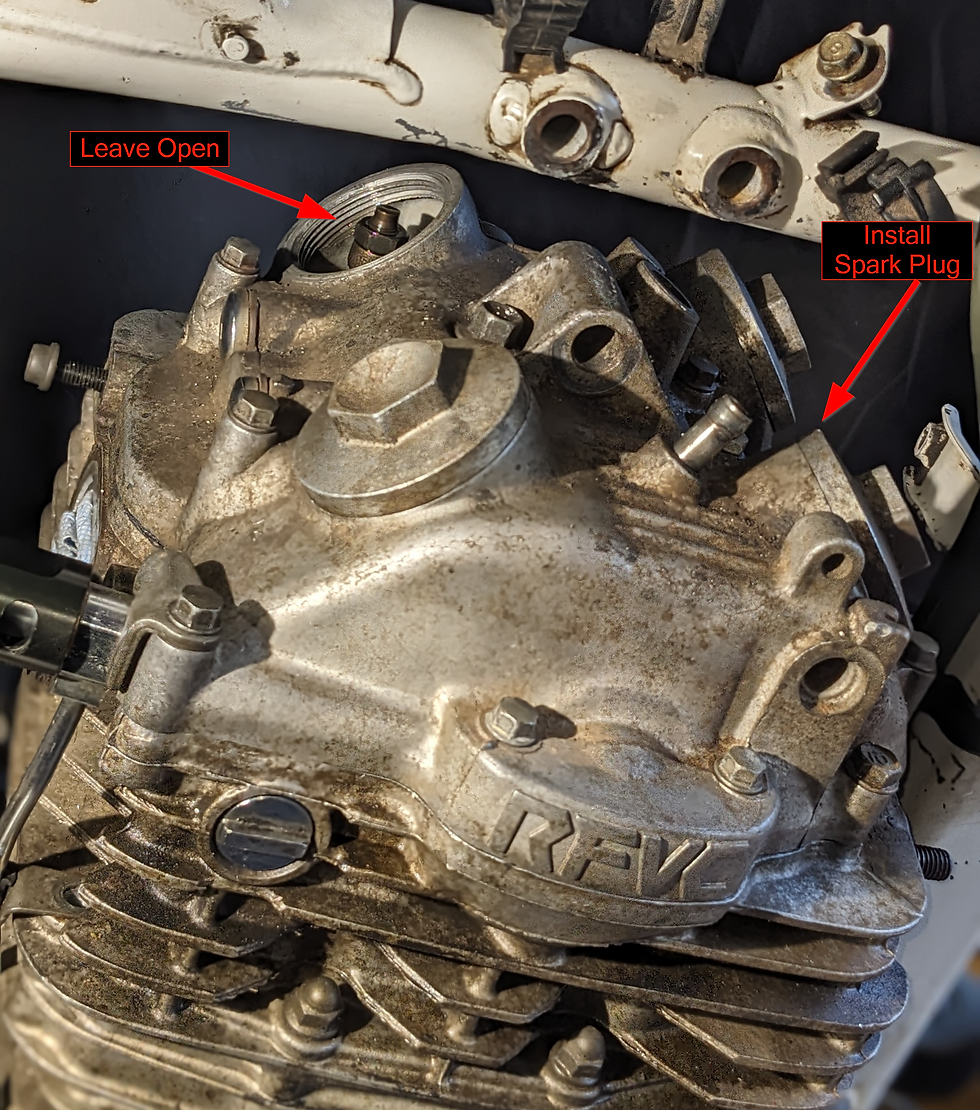
Re-install the spark plug. Now install all cylinder head cover inspection ports except for the left intake cover. This will be used to pour oil into.
Ensure the drain plug is installed on the engine. Fill the engine with oil. Note that you will be changing the oil again directly after the cam break-in is complete. It is recommended (purely from a financial standpoint) to not put a new oil filter in during the cam break-in, and to instead wait to put a new oil filter in once the break-in oil has been drained and new regular use oil is used.
Fill the engine with 2quarts of oil as indicated below. It is highly recommended to use a break-in specific oil, particularly for cam break-ins on flat tappet valvetrain engines (which is the case for the XR650L).
A great break-in oil for this process is one which contains high amounts of zinc, as well as proper amounts of phosphorous and molybdenum. Maxima high zinc content break-in oil is available here in 10W-30 weight to ensure fast oil delivery to the valvetrain during this short duration engine break-in process.

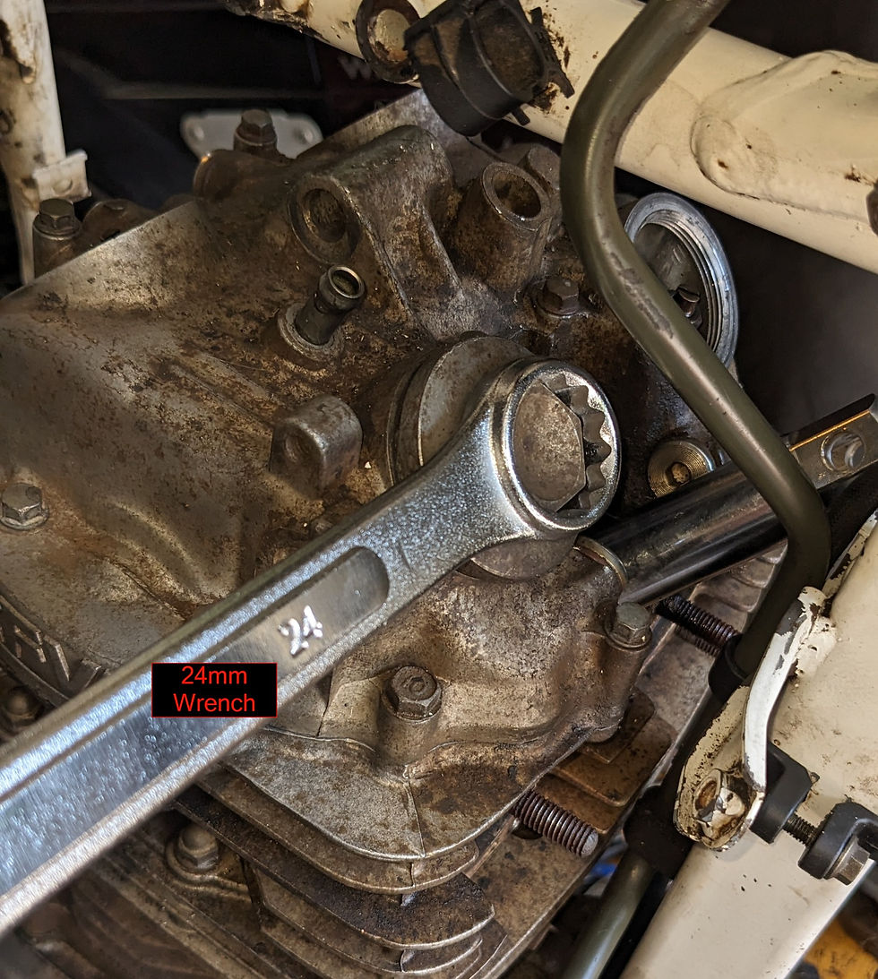
For adding the oil, pour 1.5 quarts directly into the frame as is normally done, and then add the last half quart to the valve train by pouring it directly into the open intake valve inspection port cover.

Install the final inspection cover using a 24mm closed end wrench.
Install the flywheel engine cover inspection ports using a 6mm and 10mm hex.

For the final wrap up, re-install all engine mounts using 12mm and 14mm sockets, gas tank using a 10mm socket and pliers to install fuel line, and finally the seat using a 12mm socket.
Break in
Breaking in a flat tapped cam is fairly simple, but it is critical that you follow this process as accurately as possible to ensure longevity for the valvetrain components. The engine must run within a narrow band of engine speed during the entire break-in process to ensure that the cam and cam followers wear to each other optimally, and that adequate oil flow occurs to the cam and hydrodynamic lubrication occurs.
Process Breakdown
Start engine and immediately raise the rpm to within 2,000rpm to 2,500rpm
Hold this range of rpm for 20minutes
Shut down the engine
Drain all oil while engine is still hot
Replace oil filter
Replace engine oil with non-break-in oil
Ride it like you stole it (hopefully you didn't). No further RPM restriction necessary.

Enjoy the newly added performance you've just unlocked. Questions? Don't hesitate to contact us!


Thank you for sending me the information I really appreciate it